What Are CNC Machining Parts and How Are They Made?

Time:2026-09-16 Author:Amelia
0%

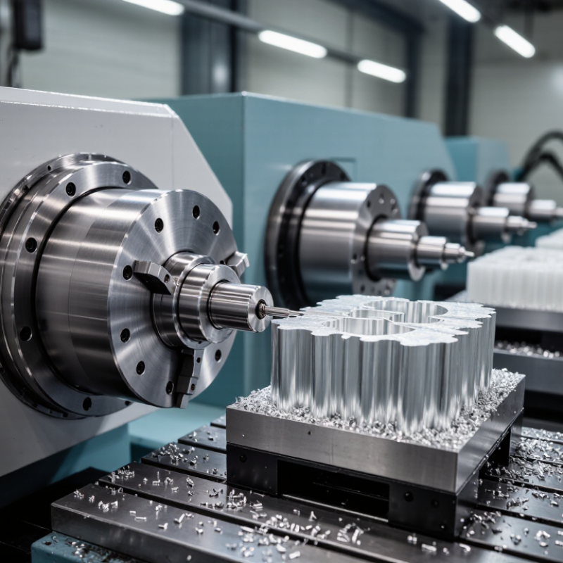
Cnc Machining Parts turn digital designs into measurable components for aerospace, automotive, medical, and industrial equipment. A CAD model guides CAM software, which generates toolpaths and G-code. The machine then removes material from an aluminum billet, steel block, or engineering plastic. Each pass leaves visible evidence: tool marks, sharp edges, and measured surfaces.

The industry is expanding with strong demand for accurate, repeatable production. Fortune Business Insights valued the global CNC machine market at approximately USD 83.99 billion in 2023 and projected it to reach USD 140.78 billion by 2032. Grand View Research also identifies automation, digital manufacturing, and complex component production as major growth drivers. These figures describe machine investment, not every Cnc Machining Parts order. That distinction matters.

Dr. Thomas Kurfess, a recognized manufacturing expert and former SME president, has said, “Manufacturing is the backbone of our economy.” His observation explains why process control matters beyond speed. A reliable part requires suitable tooling, stable workholding, correct feeds and speeds, and inspection against engineering drawings. Standards such as ASME Y14.5 support consistent interpretation of tolerances. ISO 9001 systems can strengthen traceability and corrective action.

Still, perfect results are never automatic. A small setup error can shift a hole by fractions of a millimeter. Heat can change dimensions. Even experienced machinists review assumptions. This article explains how Cnc Machining Parts are designed, programmed, machined, inspected, and improved in real production environments. Some choices remain less obvious than they appear.
What Are CNC Machining Parts and How Are They Made?

CNC Machining Parts: Definition, Materials, and ±0.005–0.1 mm Tolerances

CNC machining parts are components shaped from solid material by computer-controlled cutting tools. A digital model guides milling, turning, drilling, or boring operations. The machine removes material until the part matches the drawing. Tool selection, cutting speed, and workholding all affect the final result. That choice matters.

Common materials include aluminum, stainless steel, carbon steel, brass, titanium, and engineering plastics. Aluminum machines quickly and produces clean edges. Stainless steel resists corrosion but can generate more heat during cutting. Plastics reduce weight, yet they may deform under pressure. Material behavior must be considered before programming begins. The drawing alone is not enough.

Tolerance describes the permitted variation from a specified dimension. A tolerance of ±0.1 mm suits many brackets and general mechanical parts. A tighter ±0.005 mm tolerance demands better machines, stable temperatures, sharp tools, and careful inspection. It also increases production time and cost. Not every surface needs extreme precision.

Inspectors may use calipers, micrometers, height gauges, or coordinate measuring equipment. They check critical holes, thicknesses, flatness, and alignment. Tool wear can gradually shift dimensions between batches. Heat can change both the part and the machine. No setup is flawless. Even experienced machinists review unexpected measurements instead of ignoring them. A practical design leaves tighter tolerances only where function truly requires them.

From CAD Models to ISO 6983 G-Code Through CAM Programming

What Are CNC Machining Parts and How Are They Made?

A CNC machining part begins as a precise CAD model. The model defines holes, pockets, threads, tolerances, and surface boundaries. CAM software then converts this geometry into machining operations. It selects tools, cutting depths, feeds, speeds, and approach paths. The result is not G-code yet. A postprocessor translates the toolpath into ISO 6983-compatible commands for a specific machine controller. This step matters because identical code may behave differently across machines.

The programmer checks stock size, workholding, tool reach, and collision risks before cutting metal. Simulation can reveal a rapid move crossing a clamp or a tool entering too deeply. I have seen clean simulations fail after an incorrect work offset was entered at the machine. Small details matter. A 0.2 mm error can ruin a precision bore.

The World Robotics 2023 report recorded 553,052 industrial robot installations worldwide in 2022. That figure reflects growing automation, but CNC quality still depends on human verification. Operators compare the first part with drawings and inspection data. They confirm diameter, flatness, and surface finish. ISO 6983 remains widely recognized, although modern workflows increasingly consider richer data standards. The process is powerful, but not flawless. A perfect CAD model cannot correct poor fixturing, worn tools, or misunderstood tolerances.

What Are CNC Machining Parts and How Are They Made? — From CAD Models to ISO 6983 G-Code Through CAM Programming

Manufacturing Stage Primary Inputs Key Activities and Technical Content Typical Output Important Controls and Considerations
1. Part Design in CAD Functional requirements, dimensions, material requirements, assembly interfaces Create a precise 2D drawing or 3D solid model. Define features such as holes, pockets, slots, fillets, chamfers, threads, datums, and coordinate systems. Parametric CAD model and engineering drawing Use fully defined dimensions, clear datums, realistic wall thicknesses, and tolerances appropriate to the intended manufacturing process.
2. Design for CNC Manufacturability CAD geometry, required tolerances, available cutting tools, machine capabilities Review tool access, internal corner radii, workholding surfaces, feature depth, thin walls, deep cavities, and the need for multiple setups. Manufacturing-ready design or design revision list Internal corners generally require a radius because rotary cutting tools are round. Smaller radii and deeper cavities normally increase machining time and tool-access difficulty.
3. Material Selection and Preparation Material specification, stock dimensions, heat-treatment requirements Select bar, plate, block, tube, or near-net stock. Verify material grade, condition, dimensions, and traceability before cutting or loading. Prepared workpiece blank Stock should provide machining allowance on all required surfaces. Material properties affect cutting speed, tool wear, heat generation, and achievable surface finish.
4. CAD-to-CAM Data Transfer CAD model, drawing, revision information, manufacturing notes Import or reference the model in CAM software. Confirm units, model scale, coordinate orientation, revision status, and the intended finished geometry. CAM project containing the correct part definition Check for missing faces, gaps, duplicate geometry, incorrect units, suppressed features, and discrepancies between the solid model and drawing.
5. Workholding and Setup Planning Part geometry, stock model, machine envelope, fixture or vise arrangement Define the work coordinate system, fixture orientation, locating surfaces, clamping points, setup sequence, and any required reorientation. Setup sheet and workholding plan Avoid clamping on finished surfaces when possible. Ensure adequate rigidity, tool clearance, repeatable location, and safe access to all programmed features.
6. Tool Selection Material, feature geometry, required tolerance, surface-finish target, machine spindle and holder limits Choose drills, end mills, face mills, ball-nose tools, chamfer tools, thread mills, reamers, boring tools, or other suitable cutters. Tool list with diameters, lengths, holders, and cutting data Tool diameter and length influence rigidity, corner access, chip evacuation, deflection, and achievable dimensional accuracy.
7. CAM Toolpath Programming CAD model, stock definition, setup coordinate system, tool library, cutting parameters Create operations such as facing, roughing, adaptive or high-efficiency milling, finishing, drilling, boring, tapping, contouring, and chamfering. Ordered toolpath operations Control step-over, step-down, feed rate, spindle speed, cutting direction, lead-in, lead-out, coolant strategy, and remaining stock.
8. Toolpath Simulation and Verification Toolpaths, machine or kinematic model, stock model, fixture model, tool assemblies Simulate material removal and check for collisions, gouges, excessive tool engagement, holder interference, overtravel, and uncut material. Verified toolpath and corrected CAM program Simulation reduces programming risk but does not replace machine-side checks, dry runs, single-block verification, or operator judgment.
9. Post-Processing to G-Code Verified CAM toolpaths, target controller format, machine configuration Use a post-processor to translate CAM operations into controller-specific numerical control instructions. ISO 6983 is widely associated with the traditional G-code format used for CNC programs. Machine-readable NC/G-code program The same CAM toolpath can require different output for different machines. Confirm units, work offsets, tool changes, spindle commands, feed modes, canned cycles, and program end codes.
10. Program Review at the Machine NC program, setup sheet, tools, fixtures, drawing, inspection requirements Load the program, verify tool numbers and offsets, check work coordinate offsets, review initial moves, and perform a dry run or controlled prove-out. Approved machine setup ready for cutting Confirm clearance from the vise, clamps, fixture, stock, and machine travel limits. Verify that the selected tool length and diameter match the program.
11. CNC Material Removal Approved program, prepared stock, cutting tools, coolant or lubrication, workholding setup The CNC controller interprets programmed coordinates and commands. The machine controls axis motion and spindle operation to remove material through milling, turning, drilling, boring, or related operations. Machined CNC part or semi-finished part Monitor chip formation, vibration, tool wear, coolant delivery, cutting load, workpiece movement, and unexpected alarms during production.
12. In-Process Measurement Part features, probing or measurement equipment, process control plan Measure critical dimensions during or between operations using probes, height gauges, micrometers, calipers, bore gauges, or other suitable instruments. Offset adjustments or process acceptance data Measurement equipment must have suitable resolution, calibration status, and access. Thermal growth and measurement technique can affect results.
13. Secondary Operations Machined part, drawing, finishing requirements, approved process instructions Perform deburring, edge breaking, cleaning, heat treatment, surface treatment, grinding, marking, or assembly preparation when specified. Finished or conditionally finished component Protect critical surfaces and dimensions. Secondary processes can alter hardness, surface texture, color, flatness, or dimensional condition.
14. Final Inspection Finished part, engineering drawing, inspection plan, calibrated instruments Verify dimensions, geometric tolerances, hole locations, threads, surface finish, material condition, and visual requirements against the approved specification. Inspection report and accepted, reworked, or rejected part Use appropriate instruments such as calipers, micrometers, gauges, height gauges, optical systems, or coordinate measuring equipment according to feature complexity and tolerance.
15. Documentation and Traceability CAD revision, CAM revision, NC program, setup data, inspection records Record material identification, machine setup, tool information, program revision, inspection results, nonconformities, and corrective actions. Controlled manufacturing record Revision control prevents outdated geometry or programs from being used. Records should support repeat production and root-cause analysis.

Technical note: ISO 6983 describes a conventional method for communicating CNC machine-tool programs using coded instructions. Actual supported commands, syntax, canned cycles, coordinate behavior, and safety functions depend on the specific machine controller and post-processor configuration.

Workholding, Datum Setting, and 3-, 4-, or 5-Axis Machine Motion

CNC machining parts are shaped by programmed cutting, but accuracy begins before the spindle moves. Workholding must resist cutting forces without distorting the stock. A vise, chuck, or custom fixture should expose enough material for tool access. It should also repeat reliably. A loose clamp can ruin an otherwise correct program.

Datum setting controls the part’s relationship with the machine. Operators commonly touch off a known face, edge, or bore, then record the work coordinate. That reference affects every hole and pocket.

A 2024 CNC machine market analysis projected the sector to grow at roughly 7% annually through 2030. Such growth increases pressure for repeatable setups, not merely faster cutting. My practical concern is simple: datum selection is often treated as routine. It deserves a written inspection step.

A 3-axis machine moves along X, Y, and Z. It suits many prismatic parts, especially when features remain accessible from one direction.

A 4-axis machine adds rotation, reducing reclamping and improving feature alignment.
A 5-axis machine tilts and rotates the workpiece, allowing shorter tools and better access to angled surfaces.

The International Federation of Robotics reported 4.28 million industrial robots operating worldwide in 2023. That figure reflects broader automation, but CNC success still depends on human judgment. More axes do not automatically mean better parts. Complex motion can magnify poor fixturing, incorrect datums, or unverified tool paths. Sometimes, simpler wins.

Cutting Tools, Speeds, Feeds, and Material Removal Parameters

What Are CNC Machining Parts and How Are They Made?

CNC machining parts are shaped by removing material from a solid workpiece. A cutting tool follows programmed paths with controlled movement. Common operations include milling, turning, drilling, and boring. The final shape depends on tool geometry, machine rigidity, and material behavior. A sharp carbide tool may cut aluminum smoothly, while stainless steel needs steadier pressure and careful heat control. Small details matter.

Cutting speed describes how quickly the tool edge travels across the material. Feed rate controls how fast the tool advances through the workpiece. Spindle speed connects both factors and must match the tool diameter. A simple calculation can produce a useful starting point, but it is not a guarantee. In practice, the first setting is often imperfect. Listen for chatter. Watch the chips. Long, blue chips may signal excessive heat, while powdery chips can indicate poor cutting action. Reducing speed, feed, or depth of cut can stabilize the process.

Material removal parameters include axial depth, radial engagement, feed per tooth, and step-over. A deep cut removes material quickly but increases tool load. A lighter step-over can improve surface quality without overstressing the machine. Coolant selection, tool wear, and workholding also influence results. Experienced machinists verify dimensions with calibrated instruments during production, not only afterward. Even a reliable setup deserves review, because material hardness and tool condition can change between batches.

Inspection and Finishing: ISO 2768 Tolerances and Ra 0.8–3.2 μm Surfaces

CNC machining parts are made by removing material with computer-controlled cutting tools. After machining, inspection confirms whether each part matches the drawing. ISO 2768 tolerances provide practical limits for general dimensions without individual tolerance values. They do not replace tighter tolerances on critical features. A shaft, bracket, or housing may need closer control around mating surfaces.

Surface inspection is equally important. A Ra value of 0.8–3.2 μm describes average surface roughness, measured with a calibrated tester. Ra 0.8 μm often requires stable tooling, suitable cutting conditions, and careful finishing. Ra 3.2 μm may suit less demanding faces, but burrs and visible tool marks still require attention. Inspectors should check datum features, hole sizes, flatness, and surface finish using documented methods. A clean-looking part can still fail. Visual judgment is useful, but never enough. I sometimes find inspection plans too cautious, yet one missed feature can cause expensive rework.

Tips: Confirm the latest drawing revision before production. Measure temperature-sensitive parts in a controlled environment. Record actual readings, not only pass or fail results. When Ra values vary, check tool wear, feed rate, coolant, and measurement direction. Do not polish blindly. Polishing can change dimensions and soften sharp edges. Reflect on the process when results drift; the problem may begin before finishing.

FAQS

What are CNC machining parts?

CNC machining parts are components cut from solid material using computer-controlled tools. A digital model guides milling, turning, drilling, or boring. The machine removes unwanted material. The final shape follows the drawing.

Which materials are commonly used for CNC machining?

Common choices include aluminum, stainless steel, carbon steel, brass, titanium, and engineering plastics. Aluminum cuts quickly and leaves clean edges. Stainless steel resists corrosion but creates more cutting heat. Plastic reduces weight but may deform under pressure. Material behavior matters.

What does a tolerance of ±0.1 mm mean?

It allows the finished dimension to vary by 0.1 millimeters above or below the specified size. This tolerance suits many brackets and general mechanical parts. For example, a 20 mm feature may measure between 19.9 and 20.1 mm.

When is ±0.005 mm tolerance necessary?

This tighter tolerance suits features requiring precise alignment or controlled movement. It needs stable temperatures, sharp tools, reliable machines, and careful inspection. Production usually takes longer. Costs increase too. Extreme precision is not always useful.

How are CNC machined parts inspected?

Inspectors may use calipers, micrometers, height gauges, or coordinate measuring equipment. They check critical holes, thicknesses, flatness, and alignment. A micrometer can verify a thin edge more accurately than a basic caliper. Measurements can still surprise people.

Why are workholding and datum setting important?

Workholding must resist cutting forces without distorting the material. A vise, chuck, or custom fixture should provide tool access and repeatable positioning. Datum setting connects the part to the machine’s coordinate system. A misplaced reference can shift every hole and pocket. That mistake spreads.

What is the difference between 3-axis, 4-axis, and 5-axis machining?

A 3-axis machine moves along X, Y, and Z. It suits many parts with accessible features. A 4-axis machine adds rotation and can reduce reclamping. A 5-axis machine tilts and rotates the workpiece for angled surfaces. More axes do not guarantee better parts.

How can manufacturers reduce dimensional variation between batches?

They should monitor tool wear, temperature, workholding, and datum positions. Inspecting critical features during production can reveal gradual changes. Written datum checks are useful. No setup is flawless. I would recheck unexpected measurements instead of ignoring them.

Conclusion

Cnc Machining Parts are precision components produced by removing material from metal, plastic, or other solid stock according to a digital design. The process usually begins with a CAD model, which is converted through CAM programming into ISO 6983 G-code that controls machine movement. Engineers select suitable workholding methods, establish accurate datums, and use 3-, 4-, or 5-axis machining to reach complex surfaces and features. Depending on the material and geometry, cutting tools, spindle speeds, feed rates, and depth of cut are carefully adjusted to control material removal, accuracy, tool life, and production efficiency.

After machining, each part is inspected with appropriate measuring equipment to verify dimensions, geometric requirements, and tolerances commonly ranging from ±0.005 to ±0.1 mm. Finishing operations may include deburring, cleaning, polishing, or surface treatment. Quality evaluation can also follow ISO 2768 guidelines, while surface roughness is often specified between Ra 0.8 and 3.2 μm. Together, controlled programming, stable setup, optimized cutting parameters, and thorough inspection ensure reliable, consistent parts for demanding applications.


Amelia

Amelia

Amelia is a seasoned marketing professional with a wealth of expertise in our company’s core offerings. With an unwavering passion for driving growth and innovation, she plays a pivotal role in shaping our marketing strategies and enhancing brand visibility. A key aspect of her responsibilities......